Key takeaways
- Start depth and stopping depth describe different parts of the automatic pumping cycle.
- Read delivered flow at working head, then check the manual’s installation-height limit.
- Hose inside diameter, length, fittings and kinks affect how much water reaches the outlet.
- Use the specified strainer and maintain a clear intake path as debris accumulates.
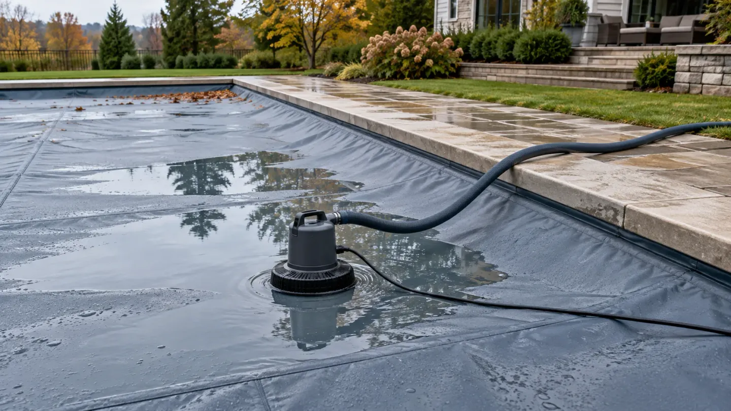
A pool cover pump needs to start in the water that collects on your cover and keep moving that water through the installed hose. Select it by water depth, working head and debris-screen access before comparing the largest gallons-per-hour number on the box.
For a closed solid cover, the useful buying question is: will this pump start, deliver enough flow through this route, and remain clear enough to keep working? Include that surface-water route in your wider pool cover plan.
Scroll horizontally to read all columns.
| Selection input | Where to get it | What it decides |
|---|---|---|
| Water depth at the collection pocket | Observe the cover; compare with the pump manual’s ON/OFF depths | Whether automatic pumping can start and how much water remains |
| Discharge elevation | Measure from the collected-water surface to the hose outlet | The elevation component of required head |
| Hose length and inside diameter | Measure the route and read the hose specification | Resistance at the intended flow |
| Adapters, bends and check valve | List the actual discharge assembly | Additional losses and backflow control |
| Leaves, needles or sediment | Inspect the cover and intake location | Strainer access and cleaning needs |
| Freezing exposure | Check the site conditions against the selected manual | Seasonal operation and storage |
Match start and stop depth to the water pocket
Compare the automatic starting depth with the water depth where the pump will sit. The stopping depth tells you what can remain after a cycle; it does not tell you how shallow the water can be when starting.
The WAYNE WAPC250 Operating Instructions and Parts Manual, 690001W-001 C 1/20, provides a useful model-specific example. Its operating instructions on page 7 specify starting at 2-1/8 inches and stopping at approximately 3/4 inch. Water below the starting threshold will not start that pump’s normal automatic cycle, even if it is deeper than the stopping level.
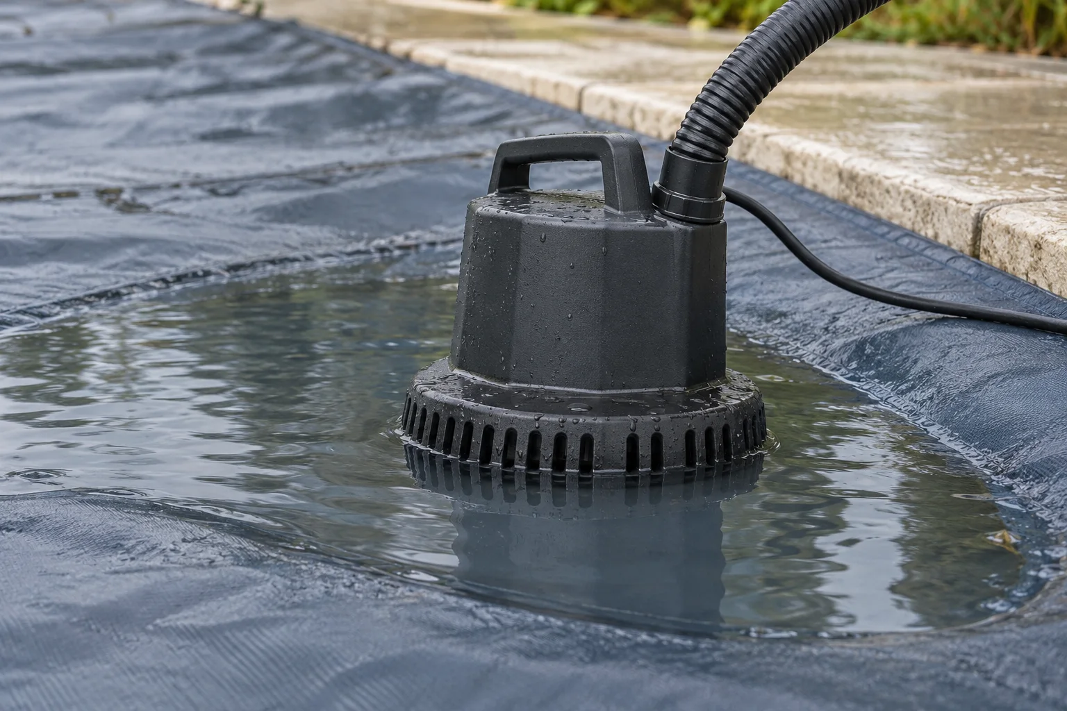
Keep the pump upright on the clean contact area specified in its manual. Inspect the cover first: the WAPC250 instructions warn that a damaged or leaking cover can give way or allow the pump to draw treated pool water. Follow the cover manufacturer’s water-removal and access instructions; a pump’s switch settings are operating specifications, not a cover load rating. Never step onto the cover to position or retrieve a pump.
Read flow at working head
Choose from the head-flow curve or table at the installed system’s duty point. Zero-head flow describes one end of the performance range. Raising the outlet and forcing water through a hose changes the flow available.
Total dynamic head expresses the energy the pump must add per unit weight of water. For a shallow water pocket open to the atmosphere discharging through a full hose into open air, with negligible surface velocity, use this energy balance:
Required head at flow Q = outlet elevation above the water surface + hose friction loss at Q + fitting losses at Q + outlet velocity head at Q.
Use consistent head units throughout, such as feet of water. A hose-loss calculation must use the actual inside diameter and include the adapters and valve. Keep the outlet convention consistent: when the calculation already includes the outlet’s velocity head, do not add a second allowance for that same energy.
The Department of Energy and Hydraulic Institute pumping sourcebook explains the connection between system requirements and pump performance. For selection, evaluate the losses at a candidate flow, compare the required head with the pump curve, and repeat until the two agree. Horizontal hose length contributes friction; it is not added foot-for-foot as vertical lift.
A manual example: flow and operating limits together
The WAPC250 manual’s page 1 performance table gives these discharge-head values. Its installation and troubleshooting instructions add the separate automatic-operation limit shown below.
Scroll horizontally to read all columns.
| WAPC250 manual specification | Value | Selection use |
|---|---|---|
| Flow at 0 ft discharge head | 3,000 US gallons per hour | Maximum listed flow at zero head |
| Flow at 5 ft discharge head | 2,350 US gallons per hour | Compare with calculated working head |
| Flow at 10 ft discharge head | 1,600 US gallons per hour | Compare with calculated working head |
| Maximum pumping height for automatic operation | 13 ft | Check the installation separately from the curve |
| Automatic start / stop depth | 2-1/8 in / approximately 3/4 in | Match the collection pocket and residual water |
If the calculated duty point is 10 feet of head, the table value to assess is 1,600 GPH. An outlet ten feet above the collected water requires additional head for the flowing hose and fittings, so that elevation alone does not establish 1,600 GPH at the hose end. The manual also lists a 15-foot performance point, but instructs owners to keep automatic installations within its 13-foot pumping-height limit. Apply both checks using the documentation supplied with the actual unit.
Choose the hose with the pump
Specify hose bore, length and connections as part of the pump choice. A garden-hose adapter makes a connection possible; the hose still affects delivered flow.
The WAPC250 manual describes a 1-1/4-inch NPT discharge and a supplied adapter/check valve with 3/4-inch hose threads. Those thread dimensions do not establish the hose’s inside diameter. As another example of a model-specific hose instruction, the Little Giant APCP-1700 Owner’s Manual, 998295 Rev. 06 03/25, page 3, recommends 1-inch inside-diameter tubing for optimal performance. Use the arrangement specified for the model you select.
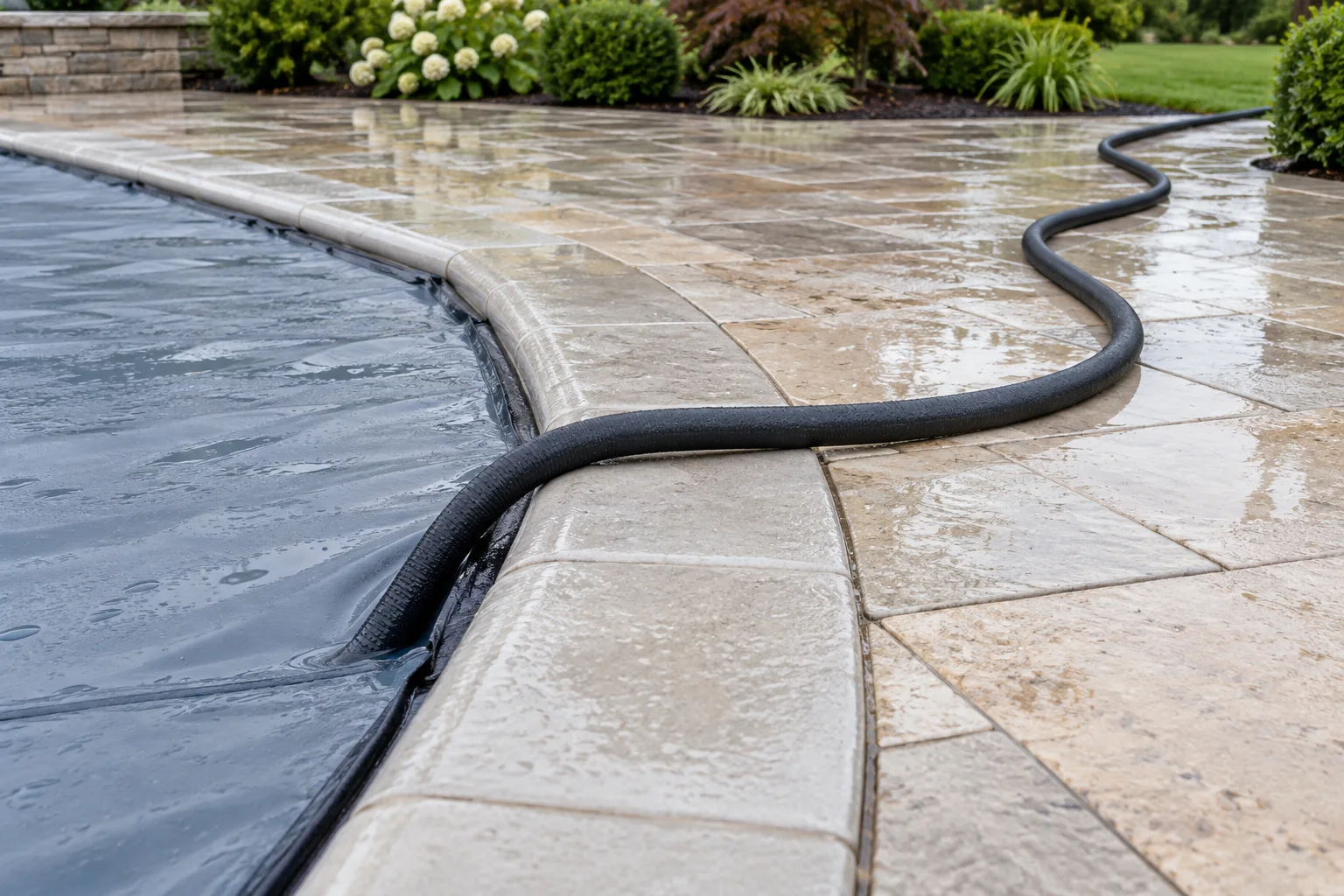
Lay out the route before buying. Unwind the hose, avoid pinching it at the pool edge, and record high points as well as the final outlet level. Route discharged water away from the cover to a destination permitted for the site. Install the specified check-valve arrangement where the manual requires it; water draining back can cause repeated starts.
For a new pool, put the hose route and cover-water pump on the equipment schedule alongside the other pool equipment decisions. For a recessed automatic cover, coordinate the separate housing drainage route too.
Choose a debris screen you can keep clear
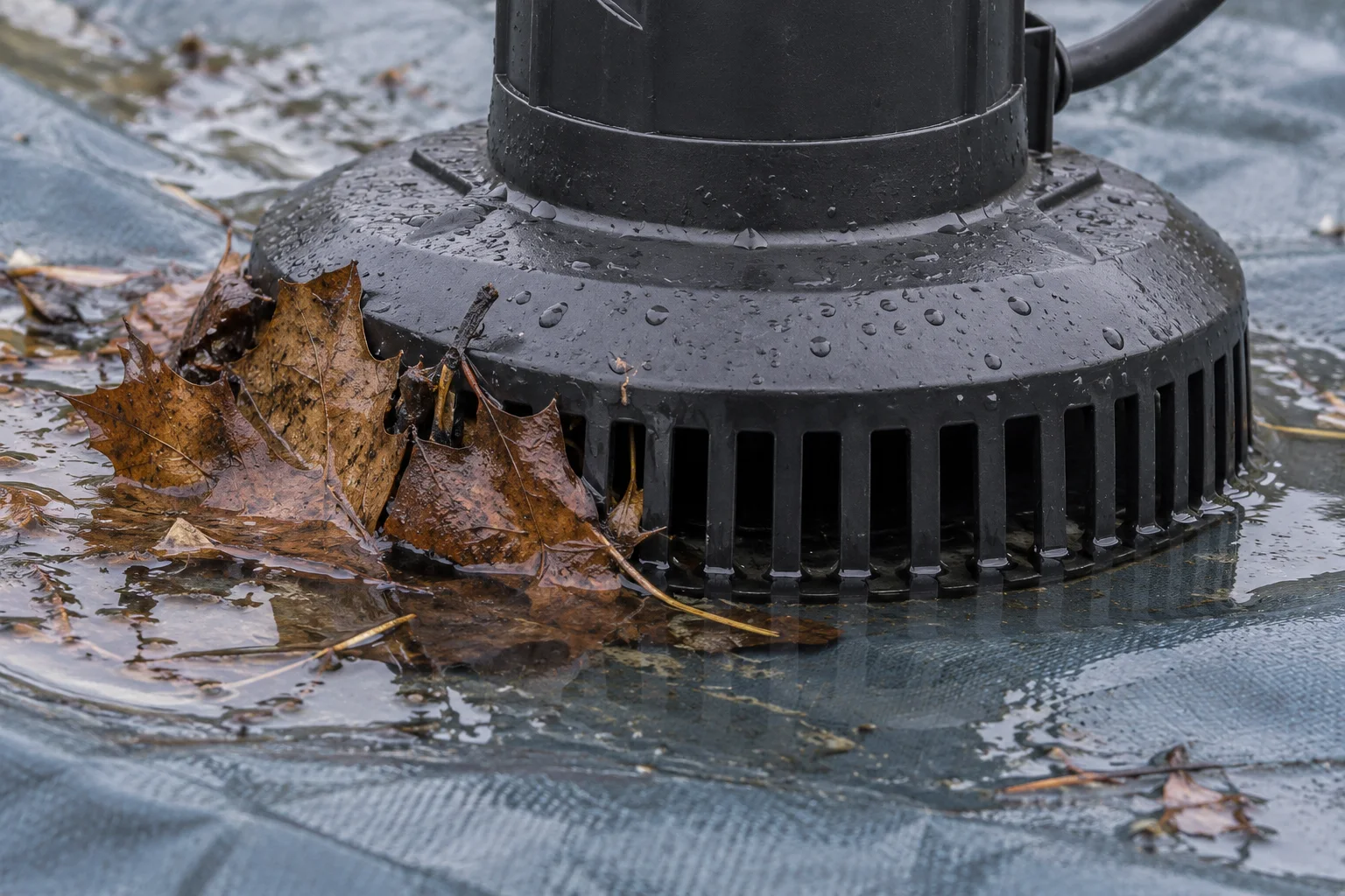
Use the pump’s specified strainer and judge how easily you can inspect and clean its water openings. The useful opening is the part water can actually reach. Leaves plastered over a large base can obstruct that path.
The WAPC250 manual, pages 5–6, calls for its snap-on debris strainer, full contact with a clean area of cover, and placement clear of mud, sand and leaves. It identifies three jobs for the strainer: filtering debris, stabilizing the pump and helping protect the cover.
Check these features when comparing pumps:
- Correct base and fit: the strainer is specified for the model, seats securely and provides the intended cover contact.
- Cleaning access: the manual explains how to remove the screen and reach debris around the intake and water sensor.
- Debris exposure: the intake location can be kept clear of leaf piles, needles and sediment.
- Approved accessories: any additional debris barrier is expressly approved for the pump and has its own maintenance instructions.
For screen sizing, use the model’s approved assembly and accessory specifications. Adding a finer fabric wrap changes the water path and can create another clogging surface. When discharge slows after leaf fall, inspect the intake and hose before deciding that a higher nominal GPH pump is needed.
Check freezing and blocked-flow behavior
Match cold-weather use to the selected manual, and check the whole water path. A motor-protection feature does not clear an iced hose or restore a blocked intake.
The WAPC250 manual, page 9, instructs users to remove the pump and store it indoors when temperatures drop below freezing. Use that instruction for that model; other pumps have their own cold-weather provisions. Check hose and pump conditions before returning the unit to service.
For weak or interrupted discharge, the practical inspection order is water depth, intake and sensor cleanliness, hose kinks or ice, then pumping height and the specified valve arrangement. Disconnect power before cleaning, repositioning or handling the pump. The WAPC250 manual specifies a properly grounded 120-volt GFCI-protected outlet. Follow the selected unit’s electrical instructions and have a qualified electrician address an unsuitable supply.
Record the inputs before choosing
Bring one site record to the model comparison. Record the water depth at the collection pocket, the hose’s full length and actual inside diameter, and the outlet elevation relative to the collected-water surface. Add a route sketch showing high points, adapters and the check valve; note the debris type and freezing exposure.
If removal time matters, also record the amount of water to remove, the desired time and whether rain is still adding water. Compare that duty with the pump’s flow at working head. Then confirm the start/stop levels, installation-height limit, approved strainer and cleaning method in the manual for the unit being purchased.
Keep those choices with the automatic pool cover planning documents so the cover, discharge route and operating instructions stay coordinated.
Frequently asked questions
Why does my automatic pool cover pump leave water behind?
Automatic pumps stop at a specified residual depth and restart at a higher depth. Check the manual for both values, then check that the pump is upright in the collection pocket and the intake and water sensor are clear. Disconnect power before handling it.
Can I use a garden hose with a pool cover pump?
Use a garden hose when the pump manual permits that connection. Check the hose’s actual inside diameter and length as well as the adapter thread. A compatible connector establishes fit; delivered flow still depends on the hose restrictions and elevation.
Should I add a finer mesh around the pump intake?
Start with the strainer specified for the pump. For fine debris, use an accessory expressly approved for that model and follow its cleaning instructions. An added fine layer can clog and restrict the water path.
Sources
- Improving Pumping System Performance: A Sourcebook for Industry — U.S. Department of Energy and Hydraulic Institute