Key takeaways
- Changing pad location or elevation after construction may require new work; check it before the pour.
- Long or convoluted pipe runs cost flow and energy for the life of the pool.
- Every unit needs listed clearances for service, venting, or airflow, not just room to stand.
- Reserve pad space and conduit for future rows — heat, automation, cover drive — even if they are deferred.
A poorly placed pad can require excavation to move. Use the equipment list and equipment guide to settle locations, levels and routes before concrete.
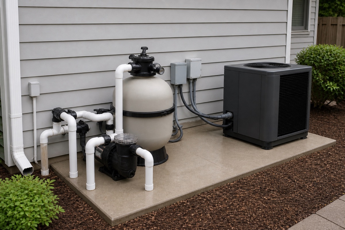
Location: hydraulics first, then everything else
Have the designer compare the hydraulic route with drainage, setbacks and access. Record these separately:
- Elevation. Surrounding grade is the ground draining toward or away from the pad. Static water level is the pool water surface at rest. Operating hydraulic grade line represents piezometric head along the system; it is not a default pad datum. Check runoff protection separately from suction lift or flooded suction.
- Noise and setbacks. Pumps and heat pumps make noise. Check applicable setbacks and noise rules.
- Fuel and power. A gas heater needs a fuel line and venting clearances. A heat pump needs open airflow. Confirm the applicable circuits and bonding on the electrical plan.
- Service access. Keep the documented working spaces accessible.
Takeaway: Establish runoff protection and hydraulic elevation as separate checks.
Laying out the pad itself
A manufacturer’s MasterTemp guide, P/N 472592 Rev. Q (July 30, 2023), Section 3 / Figure 4 and Chemical Feeders, places its chemical feeder downstream of the heater with a chemical-resistant one-way check valve between them to prevent back-siphoning. This is a documented example; confirm the actual heater and treatment combination rather than applying one sequence to every salt, UV or ozone system. Leave the manufacturer-listed clearance at each unit. Filter lids need lift-off height, heaters need venting distance, and heat pumps need air on the intake and discharge sides.
Calculate future reservations from candidate equipment outlines plus required service and exhaust/airflow spaces, including vertical access; there is no fixed square-metre allowance. An automation panel, a future heater, or an automatic cover’s powerpack may need a permitted location and a conduit path, and the cheap moment to provide both is while the trench is open. The same applies to a cover pump discharge and the fill line for an automatic fill system.
For example, public IntelliFlo3 VSF/IntelliPro3 VSF guide P/N 356231 Rev. E (June 30, 2025), Installation, distinguishes pump height above water, flooded-suction valves and motor/drive access. Clean & Clear Plus guide P/N 178558 Rev. U (May 10, 2023), Filter Location / Table 2, gives model-specific vertical removal space. Use the selected model and revision, not those dimensions for other equipment.
Takeaway: Calculate the reservation from real equipment and access envelopes.
Put it on the drawings
Pad elevation, drainage direction, pipe routes, and reserved space belong on the construction drawings next to the shell details. The construction sequence closes these paths at the electrical-and-pad stage. Record the final layout, model by model, in the pool equipment BOM template so the schedule and the pad stay one document.
Takeaway: Keep the filled plan and BOM on the same revision.
What this page does not decide
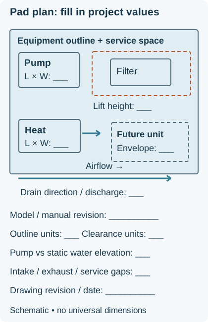
Exact pump sizing, circuit design, and code clearances are calculations for your builder, electrician, and inspector, using the real equipment manuals. Use this layout logic so those calculations still have room on the pad.
Frequently asked questions
How far from the pool can the equipment pad be?
Verify local setbacks and the selected manual's placement requirements, then have the designer check pipe losses and suction lift using the actual water level and route. A shorter route does not override required separation or service access.
Should the pad be higher or lower than the pool?
Separate surrounding ground level from the pool static water level and the operating hydraulic grade line. Grade controls runoff; pump height relative to static water affects suction lift or flooded suction. Have the designer check the selected pump's lift/priming limits, flooded-suction isolation and site drainage; there is no universal above-pool default.
How much space should I leave?
More than the current equipment needs. Manufacturer manuals list clearances for filter lid removal, heater venting, and heat-pump airflow. Add room for a future heater, automation panel, or automatic-cover power unit, plus space for a person to stand and work at each unit.
Sources
- IntelliFlo3 VSF / IntelliPro3 VSF Installation and Maintenance Guide, P/N 356231 Rev. E (June 30, 2025), Installation and Technical Data — Pentair
- Clean & Clear Plus Installation and User Guide, P/N 178558 Rev. U (May 10, 2023), Filter Location / Table 2 — Pentair
- MasterTemp Installation and User Guide, P/N 472592 Rev. Q (July 30, 2023), Section 3 / Figure 4 / Chemical Feeders — Pentair
- Hydraulic grade line, glossary definition (checked October 8, 2026) — U.S. Bureau of Reclamation