Key takeaways
- Size the concrete slab for service and code envelopes—not just base footprints—starting at 5×10 ft for heated pools and 5×12 to 6×14 ft for pool/spa combinations.
- Keep suction manifold water velocity at or below 6 ft/sec (ISPSC Section 311) and provide at least 5× pipe diameter of straight horizontal pipe ahead of the pump suction inlet.
- Install Schedule 80 CPVC headers, a 12-inch elevated Hartford loop, and a chemical-resistant check valve between the heater outlet and the saltwater chlorine generator.
- Feed variable-speed pumps continuous 240V power via a Class A GFCI breaker (NEC 680.21(C)) and switch speeds over an RS-485 serial bus while interlocking the salt cell transformer to the filter pump relay.
- Maintain an unobstructed 36-inch deep by 30-inch wide by 78-inch high NEC 110.26(A) working space in front of the automation load center and bond all metallic equipment to a continuous #8 AWG solid copper grid (NEC 680.26).
Undersizing a pool equipment pad or crowding PVC manifolds into the electrical service zone causes severe pump cavitation, heat-exchanger corrosion, and failed municipal inspections that require costly concrete and plumbing rework. A code-compliant equipment pad enforces a strict hydraulic sequence—from the suction manifold and 5×D straight pump entry run through the variable-speed pump, filter, heater, Hartford loop check valve, and saltwater chlorine generator—while preserving full NEC Article 680 and NEC 110.26 electrical clearances.
While our introductory equipment pad placement guide addresses yard location and acoustic setbacks, this engineering blueprint provides the structural slab dimensions, pool plumbing manifold layout mathematics, heat-exchanger back-siphon protection, and automation subpanel wiring rules needed before trenching begins. Coordinate these specifications with the broader pool equipment guide, the pool construction hub, and your project’s pool equipment BOM template.
Scroll horizontally to read all columns.
| Design Parameter | Code / OEM Standard | Engineering Requirement & Threshold | Dominant Failure Mode & Prevention |
|---|---|---|---|
| Concrete Pad Footprint | OEM Service Envelopes | 4×8 ft (Single Body) • 5×10 ft (Heated Pool) • 5×12 to 6×14 ft (Pool/Spa + Cover) |
Crowded components block filter lid lift or encroach into subpanel zone → size slab for clearance envelopes before pouring |
| Suction Manifold Velocity | ISPSC Section 311 / ANSI/APSP-15 |
≤ 6 ft/sec (≤ 5 ft/sec preferred per Charlotte Pipe); 2.5" Sch 40 PVC max 90 GPM |
Impeller cavitation, suction entrapment hazard, and high TDH → upsize collector header to 2.5" or 3.0" Sch 40 PVC |
| Pump Suction Straight Run | Pentair P/N 356231 Rev. E |
≥ 5 × Nominal Pipe Diameter (10" for 2.0", 12.5" for 2.5", 15" for 3.0" PVC) |
Asymmetric turbulence erodes impeller eye and corrupts flow sensor → eliminate street 90° elbows at pump inlet union |
| Filter Vertical Clearance | Pentair P/N 178558 Rev. U |
62"–72" unobstructed vertical height above slab; 50 PSI max working pressure |
Eaves or overhead piping prevent tank lid and cartridge extraction → verify vertical envelope on elevation drawings |
| Heater-to-SWG Protection | Pentair P/N 472592 Rev. Q (Fig. 4) |
Schedule 80 CPVC headers (>140°F soak) + 12" Hartford loop + CPVC check valve before SWG |
Acidic/chlorinated brine back-siphons into copper heat exchanger during off-cycle → install spring check valve + thermal loop |
| Gas Heater Exhaust Clearance | ANSI Z21.56 / NFPA 54 |
≥ 4 ft (1.2 m) from windows/air intakes (forced draft); ≥ 6 in from combustible walls |
Flue gas recirculation into building openings or fence scorching → stake heater exhaust vector before gas rough-in |
| Subpanel Working Space | NFPA 70 (NEC) 110.26(A) |
36 in. deep × 30 in. wide × 78 in. high unobstructed front service box (≥ 90° door swing) |
Failed electrical inspection requiring manifold cut-out → route all PVC risers outside the 36-inch subpanel footprint |
| GFCI, Bonding & Pump Drive | NEC 680.21(C), 680.26 & 10 CFR 431.465 |
Continuous 240V Class A GFCI + RS-485 control (≥ 0.711 HHP VSP) + "#8 AWG" bare copper grid |
Nuisance trips, stray voltage gradients, or energized dry salt cell → interlock SWG relay to pump and bond all lugs |
1. Concrete Equipment Pad Sizing, Structural Spec & Elevation Datum
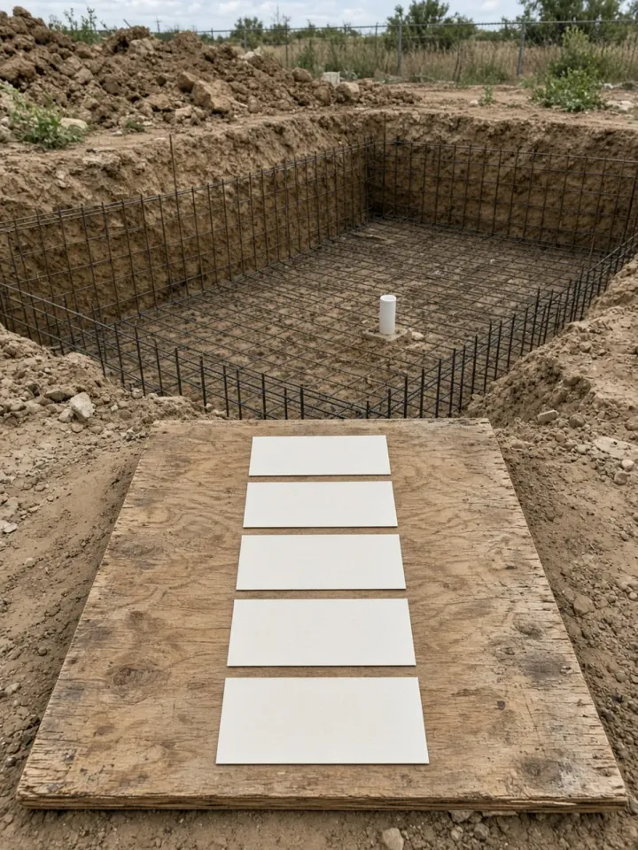
Size the concrete pad from the combined service, airflow, and electrical clearance envelopes of every planned and deferred component, never from base footprints alone. A circulation pump, cartridge filter, and gas heater occupy less than 14 sq. ft. of physical base area, yet their mandatory maintenance walkways, 5×D straight pipe runs, and electrical working clearances demand 40 to 84 sq. ft. of slab area. Review the full pool equipment list before setting formwork dimensions.
Scroll horizontally to read all columns.
| System Tier & Equipment Scope | Minimum Concrete Slab Dimensions | Slab Area | Reserved Conduits & Clearances Included |
|---|---|---|---|
| Tier 1: Compact Single-Body Pool (VSP + Cartridge Filter + SWG + Automation Panel) | 4 ft × 8 ft (48" × 96") |
32 sq. ft. |
12.5" straight suction run, 62"–72" vertical filter lift, 36" × 30" subpanel clear zone |
Tier 2: Standard Heated Pool (Tier 1 + 400k BTU/hr Gas Heater or Heat Pump + 2 Actuators) |
4 ft × 10 ft to 5 ft × 10 ft (60" × 120") |
40–50 sq. ft. |
Adds CPVC heater headers, 12" Hartford loop, check valve, 4 ft gas vent clearance or 24"–36" heat pump radial airflow |
| Tier 3: Pool/Spa Combo + Features (Tier 2 + Dual Manifolds + Jet/Feature Pump + Cover Powerpack) | 5 ft × 12 ft to 6 ft × 14 ft (72" × 168") |
60–84 sq. ft. |
Adds 4-valve suction/return manifolds, auxiliary pump straight run, automatic pool cover drive bay, and automatic fill valve |
Structural Slab & Drainage Specification
Cast the equipment pad as a monolithic 3.5-inch to 4.0-inch Portland cement concrete slab (3,000–3,500 PSI minimum 28-day compressive strength) reinforced with "#3" deformed steel rebar on 18-inch centers or 6×6 W2.9×W2.9 welded wire reinforcement over a 4-inch compacted crushed-aggregate base. Set the top of the slab 2 to 3 inches above surrounding finish grade and pitch the surface 1/8 inch to 1/4 inch per foot away from adjacent building foundations so filter washdown water and rain runoff never submerge the pump motor frame. Anchor the pump and heater chassis with stainless-steel wedge or sleeve anchors after verifying final union alignment.
Hydraulic Datum: Flooded Suction vs. Suction Lift
Separate surface runoff grading from the hydraulic elevation of the pump strainer pot relative to the pool’s static water level:
- Standard Suction Lift (Pad Above Pool Water Level): Most residential equipment pads sit
6 to 36 inchesabove the pool design water line. Self-priming filtration pumps listed under the Pentair IntelliFlo3 VSF Installation Guide handle static suction lifts up to10 feet(3.0 m) at sea level when suction piping is airtight and sized for≤ 6 ft/secvelocity, though every vertical foot of lift adds static head and extends priming duration. - Flooded Suction (Pad Below Pool Water Level): On sloped lots where the equipment pad sits below the pool water surface, opening the pump hair-and-lint strainer pot without isolation causes uncontrolled gravity siphoning from the vessel. Flooded-suction installations require positive-seal 2-way isolation diverter valves on both the suction header and discharge riser, plus an elevated loop on the automatic pool fill system and air-bleed lines above the static spillover elevation.
Rule of thumb: If the pump volute elevation sits more than 36 inches above the pool static water line, install a high-flow CPVC spring check valve on the suction riser below the manifold collector to prevent column drain-back when the pump pauses, and upsize the buried suction trunk by one nominal pipe size to preserve Net Positive Suction Head Available (NPSHa).
Takeaway: Pour a reinforced 5×10 ft or larger slab pitched 1/8 inch per foot above grade, and verify whether the pump operates under suction lift or flooded suction before finalizing manifold valve placement.
2. Pool Plumbing Manifold Layout & Straight Suction Pipe Math (ISPSC Section 311)
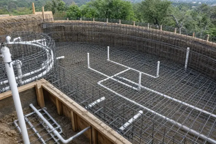
A low-head pool plumbing manifold layout pairs parallel collector branches capped at ≤ 6 ft/sec suction velocity with an unobstructed ≥ 5×D straight horizontal pipe entry into the pump. Constricted manifolds and tight 90-degree street elbows right at the pump union are the primary root causes of impeller cavitation, acoustic whine, and inaccurate onboard flow-sensor telemetry.
Velocity Caps & Schedule 40 PVC Flow Capacity
Under the International Swimming Pool and Spa Code (ISPSC) Section 311 and ANSI/APSP/ICC-15, residential circulation piping must keep water velocity at or below 6.0 ft/sec (1.83 m/s) on suction lines and 8.0 ft/sec (2.44 m/s) on pressurized return lines. Furthermore, the Charlotte Pipe Plastics Technical and Installation Manual (TM-PL) recommends designing thermoplastic suction headers for ≤ 5.0 ft/sec to suppress water-hammer surge pressure during rapid valve actuation.
Fluid velocity V (in ft/sec) through a circular pipe of inside diameter ID (in inches) at flow rate Q (in GPM) follows the continuity equation:
Velocity (ft/sec) = 0.4085 × Flow Rate (GPM) ÷ ID²
Solving for maximum flow rate Q across standard Schedule 40 PVC inside diameters yields the governing manifold sizing table:
Scroll horizontally to read all columns.
| Nominal Sch 40 PVC Size | Average Inside Diameter (ID) |
Max Suction Flow @ 5 ft/sec (Charlotte Pipe) |
Max Suction Flow @ 6 ft/sec (ISPSC Section 311) |
Max Return Flow @ 8 ft/sec (ANSI/APSP-15) |
Minimum 5×D Straight Suction Run (Pentair) |
|---|---|---|---|---|---|
1.5 inch |
1.590 in. |
31 GPM |
38 GPM |
50 GPM |
7.5 in. (Use only on individual return branches) |
2.0 inch |
2.047 in. |
51 GPM |
63 GPM |
84 GPM |
10.0 in. (5 × 2.0") |
2.5 inch |
2.445 in. |
73 GPM |
90 GPM |
119 GPM |
12.5 in. (5 × 2.5") |
3.0 inch |
3.042 in. |
113 GPM |
138 GPM |
184 GPM |
15.0 in. (5 × 3.0") |
Worked Calculation: Pool/Spa Suction Collector & 5×D Straight Run
Consider a residential pool and spa combination where the spa jet/heating mode requires 78 GPM and high-speed filtration with an auxiliary waterfall requires 72 GPM:
- Collector Header Sizing: Checking
78 GPMagainst2.0-inchSchedule 40 PVC (ID = 2.047 in.):Velocity = 0.4085 × 78 ÷ (2.047)² = 31.86 ÷ 4.19 = 7.60 ft/sec— FailsISPSC Section 311(> 6.0 ft/sec), causing high suction vacuum and cavitation. - Upsizing to
2.5-inchSchedule 40 PVC (ID = 2.445 in.):Velocity = 0.4085 × 78 ÷ (2.445)² = 31.86 ÷ 5.978 = 5.33 ft/sec— PassesISPSC Section 311(≤ 6.0 ft/sec) with a90 GPMceiling. - Minimum Straight Suction Entry Length (
L_min): Per the Pentair IntelliFlo3 VSF Installation Manual, the straight horizontal pipe between the final 3-way collector diverter valve (or sweep elbow) and the pump suction union must satisfy:Straight Suction Length = 5 × Nominal Pipe Diameter = 5 × 2.5 in. = 12.5 inches minimum
Manifold Construction Best Practices
- Individual Home-Run Risers: Bring each suction trunk (Skimmer 1, Skimmer 2, Dual Main Drain, Spa Suction) up through the soil beside the slab as an independent vertical riser equipped with its own 2-way or 3-way never-lube diverter valve (
1.5"×2.0"or2.0"×2.5"). Complete and document the hydrostatic pressure test before gunite before tying the risers into the pad equipment. - Sweep 90° Elbows Over Tight 90s: Replace tight standard 90° PVC elbows (
equivalent length ≈ 5.7 ftin2.0"pipe) with long-radius sweep 90° elbows (equivalent length ≈ 3.5 ft) across all suction and return manifold turns, cutting fitting friction head loss by 35%–40%. - High-Temperature Barrel Unions: Install threaded high-temperature barrel unions with captive EPDM O-rings at the pump suction inlet, pump discharge port, filter inlet/outlet, and heater headers so any component can be unbolted for bench repair without sawing away the
5×Dstraight pipe reserve.
Takeaway: Size the suction collector header for ≤ 6 ft/sec (2.5-inch Schedule 40 PVC for 64–90 GPM systems) and leave a full 10.0 to 15.0 inches (5×D) of straight horizontal pipe ahead of the pump inlet union.
3. Canonical Equipment Pad Sequence & Heater Protection (Hartford Loop + Check Valve + SWG)
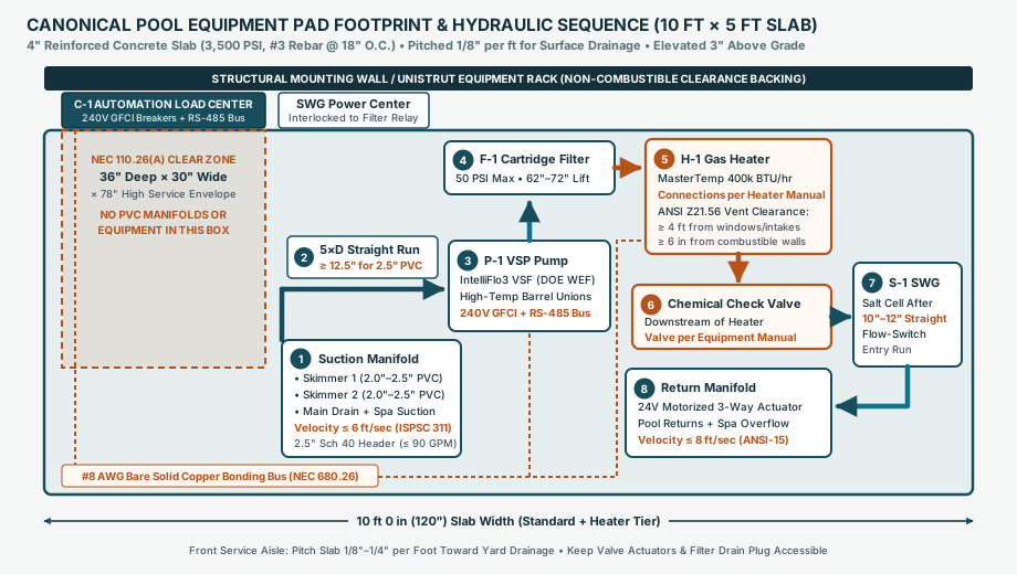
Every component on the equipment pad must be piped in strict downstream order (Pump -> Filter -> Heater -> Check Valve + Hartford Loop -> Saltwater Chlorine Generator -> Return Manifold) so that raw debris never fouls the heater and concentrated chlorine never back-siphons into the heat exchanger. Reversing or omitting a single isolation element between the heater and sanitizer is the leading cause of premature copper heat-exchanger failure.
Step-by-Step Downstream Equipment Order
- Suction Manifold &
5×DStraight Run: Combines isolated skimmer, main drain, and spa suction risers into a laminar horizontal stream entering the pump strainer pot. - Variable-Speed Filtration Pump (
P-1): Draws water from the suction manifold and pressurizes the pad loop. - Cartridge, DE, or Sand Filter (
F-1): Captures suspended particulates before water enters narrow heater tubes or salt cell plates. Per the Pentair Clean & Clear Plus Cartridge Filter Installation Guide (P/N 178558 Rev. U, Table 2), orient the tank so the pressure gauge and manual air-relief valve face the front service aisle, never exceed the50 PSImaximum working pressure rating, and preserve62 to 72 inchesof unobstructed vertical clearance above the slab to lift the upper fiberglass tank shell and internal cartridge cluster straight out. - Forced-Draft Gas Heater or Heat Pump (
H-1): Receives clean filtered water. Plumb the heater inlet and outlet with Schedule 80 CPVC nipples/headers (minimum 12–18 incheson both sides) rather than standard white Schedule 40 PVC. As documented in the Charlotte Pipe Technical Manual (TM-PL), standard PVC pressure ratings derate sharply above140°F(60°C), whereas Schedule 80 CPVC is rated up to200°F(93°C) and resists joint creep during post-shutdown heat soak if flow stops abruptly. - Elevated Hartford Loop + Chemical-Resistant CPVC Check Valve: Installed immediately downstream of the heater outlet header and upstream of any sanitizer.
- Saltwater Chlorine Generator (
S-1SWG Cell) or Chemical Feeder: Positioned at the end of the equipment train immediately before the return manifold. Provide10 to 12 inchesof straight pipe directly ahead of the salt cell inlet union so water flows evenly across its internal mechanical flow/temperature switch, and mount the cell with barrel unions for periodic scale inspection and winter bypass plug insertion. - Motorized Return Actuator & Return Manifold: Splits sanitized, heated water between pool wall/floor returns, spa return jets, spa spillover lines, and pressure-side water features at velocities
≤ 8 ft/sec.
Why the Hartford Loop and Check Valve Between Heater and SWG Are Mandatory
Per the Pentair MasterTemp Heater Installation Guide (P/N 472592 Rev. Q, Section 3 / Figure 4), installing a saltwater chlorine generator or tablet erosion feeder without positive backflow isolation creates two destructive failure modes during pump off-cycles:
- Chemical Back-Siphoning & Brine Stratification: Residual chlorine gas (
Cl₂), hypochlorous acid (HOCl), and dense hyper-chlorinated brine accumulating inside an unvented salt cell or erosion feeder migrate upstream along the bottom of horizontal piping. When low-pH, high-oxidizer water reaches the heater’s copper or cupronickel finned-tube heat exchanger, it strips the protective oxide film, eats pinholes through the tubing walls, and deposits green copper cyanurate/carbonate stains across the pool plaster. - Convective Thermal Siphoning: Hot water remaining in the heat exchanger after burner shutdown rises into downstream plastic enclosures unless trapped by a vertical elevation break.
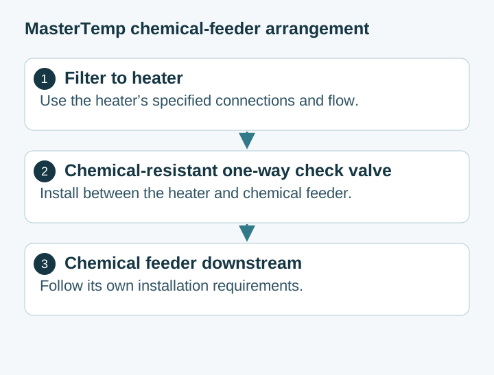
Combining a 12-inch elevated Hartford loop (a vertical inverted-U thermal siphon trap constructed with sweep 90° elbows rising at least 12 inches above the heater outlet header before dropping to the sanitizer elevation) with a chemical-resistant CPVC flapper/spring check valve (1/2-lb Hastelloy or stainless spring with Viton seals and a clear service lid) provides dual-barrier protection. For high-efficiency variable-speed systems, add an automated or spring-loaded external heater bypass loop between the filter outlet and heater outlet check valve so low-RPM filtration flows bypass the heater’s internal water header restriction when heating is not called.
Gas Heater Venting & Heat Pump Airflow Clearances (ANSI Z21.56 & NFPA 54)
- Forced-Draft Gas Heaters (
ANSI Z21.56/NFPA 54): Outdoor gas heater exhaust discharges must maintain at least4 feet (1.2 m)of horizontal and vertical clearance from any operable window, door, gravity building air intake, or HVAC louver, and at least6 inchesfrom combustible walls or wood fencing. Never tuck an outdoor forced-draft gas heater beneath a low deck overhang without an approved positive-pressure Category I/III vent kit. - Electric Heat Pumps: Air-source pool heat pumps move
2,500 to 4,000 CFMof ambient air across their evaporator coils. Maintain12 to 24 inchesof radial intake clearance around the perimeter coil and36 to 60 inchesof unobstructed discharge clearance (horizontal or vertical fan throw) so cold exhaust air does not recirculate into the intake louver and ice the evaporator.
Rule of thumb: If the equipment pad sits within 4 feet of a house window or property-line fence, place the filter and pump closest to the structure (outside the NEC 110.26 subpanel box) and position the gas heater at the outer pad edge so its exhaust terminal clears all building openings by ≥ 48 inches.
Takeaway: Protect the heater heat exchanger with Schedule 80 CPVC headers, a 12-inch elevated Hartford loop, and a CPVC spring check valve upstream of the saltwater chlorine generator, and provide 10–12 inches of straight pipe into the salt cell flow switch.
4. DOE 10 CFR § 431.465 Pump Efficiency, NEC Article 680 Bonding & Automation Subpanel Layout
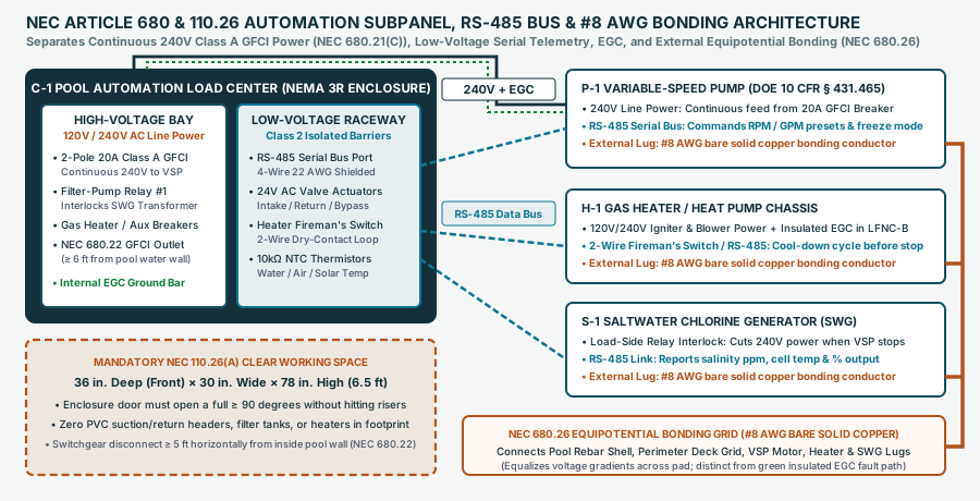
Modern equipment pad electrical design separates continuous 240V Class A GFCI branch power from low-voltage RS-485 serial speed control, interlocks the saltwater chlorine generator to the filter-pump relay, and bonds every metallic chassis to a continuous #8 AWG solid copper grid. Treating a variable-speed pump like a legacy single-speed motor—or routing PVC headers in front of the automation load center—creates code violations and hazardous operating states.
Federal Variable-Speed Pump Mandate (10 CFR § 431.465) & Pump Affinity Laws
Under the U.S. Department of Energy regulation 10 CFR § 431.465 (Dedicated-Purpose Pool Pumps), self-priming pool filtration pumps with hydraulic output power ≥ 0.711 HHP (roughly 1.15–1.5 THP and above) must meet mandatory Weighted Energy Factor (WEF, measured in kgal/kWh) standards that require variable-speed drive technology. Furthermore, 10 CFR § 431.465(g) stipulates that any integral freeze-protection control must ship disabled or with a default activation threshold no higher than 40°F (4.4°C).
As detailed in the DOE Dedicated-Purpose Pool Pumps technical guidance, centrifugal pool pumps obey the Pump Affinity Laws linking shaft speed (RPM), flow rate (Q), total dynamic head (TDH), and shaft brake power (P):
Flow Ratio: Q₂ ÷ Q₁ = (RPM₂ ÷ RPM₁)Head Ratio: TDH₂ ÷ TDH₁ = (RPM₂ ÷ RPM₁)²Power Ratio: P₂ ÷ P₁ = (RPM₂ ÷ RPM₁)³
Because power consumption varies with the cube of shaft speed, cutting pump speed in half (from 3,000 RPM to 1,500 RPM) reduces flow by 50%, reduces system friction head by 75%, and cuts electrical wattage by 87.5% ((0.5)³ = 0.125). A 2.5-inch sweep-elbow manifold allows daily filtration turnover at 1,400–1,750 RPM (28–38 GPM at 150–230 Watts), while the automation controller automatically steps the pump up to 2,500–3,000 RPM (55–80 GPM) only when the gas heater pressure switch, solar loop, or spa hydrotherapy jets demand higher flow.
Scroll horizontally to read all columns.
| Operating Mode | Typical VSP Speed / Flow | Active Pad Components | Automation Control Signal (RS-485 & Relays) |
|---|---|---|---|
| Daily Skim & Sanitize (Pool Low) | 1,500–1,750 RPM (30–38 GPM) |
VSP + Filter + Heater Bypass + SWG Cell | RS-485 Speed Preset 1 • Filter Relay CLOSED (energizes SWG above 20–25 GPM flow switch threshold) |
| Pool / Spa Heating Boost | 2,400–2,750 RPM (55–68 GPM) |
VSP + Filter + Gas Heater / Heat Pump + SWG | Heater call closes 2-wire Fireman’s Switch + commands RS-485 Heater Boost RPM to close heater water pressure switch |
| Spa Jets & Spillover Mode | 2,850–3,250 RPM (70–88 GPM) |
VSP + Filter + Heater + Motorized 3-Way Valves | 24V AC Intake & Return actuators rotate to Spa loop; RS-485 commands Spa High RPM |
| Heater Cool-Down & Off-Cycle | 1,800 RPM for 3–5 min → 0 RPM |
VSP circulates post-burn cool-down, then stops | Automation opens Heater Fireman’s Switch 3–5 min before stopping VSP; Filter Relay OPENS to cut 240V to SWG |
Freeze Protection (≤ 40°F Air) |
1,600–2,000 RPM (35–45 GPM) |
VSP + Motorized Valves cycle Pool/Spa every 15–30 min |
Triggered by ambient air thermistor ≤ 40°F per 10 CFR § 431.465(g); SWG cell remains inactive in cold water |
High-Voltage GFCI vs. Low-Voltage RS-485 & SWG Interlock Wiring
- Continuous 240V Class A GFCI Feed (
NEC 680.21(C)): Under NFPA 70 (NEC) Article 680.21(C), all single-phase120V through 240Vbranch circuits supplying pool pump motors must be protected by a Class A Ground-Fault Circuit-Interrupter (GFCI, 5 mA trip threshold). Wire the variable-speed pump directly to the load terminals of a dedicated 2-pole 20A GFCI breaker inside the automation load center so its onboard drive electronics retain continuous line voltage. - RS-485 Serial Control in Isolated Low-Voltage Raceway: Route the pump’s 4-conductor
22 AWGshieldedRS-485communication cable, the24V ACmotorized valve actuator cables, the heater’s 2-wire low-voltage fireman’s switch loop, and the10kΩwater/air/solar temperature thermistor leads through the automation enclosure’s dedicated low-voltage knockouts and Class 2 barrier raceway—never inside the same conduit as120V/240Vpower conductors. - Mandatory Saltwater Chlorine Generator Relay Interlock: Even though the saltwater chlorine generator cell incorporates an internal mechanical flow switch, primary safety requires wiring the
120V/240VAC input of the SWG power center transformer through the load side of the automation panel’s primary Filter-Pump Relay. If the mechanical flow switch ever sticks closed with calcium scale while the pump is off, the open filter-pump relay guarantees the titanium cell plates cannot generate explosive hydrogen and chlorine gas pockets inside stagnant PVC pipe.
NEC 110.26(A) Subpanel Clearances & NEC 680.26 #8 AWG Bonding Grid
Coordinate the electrical rough-in with our pool equipotential bonding inspection guide and verify three non-negotiable code clearances on the equipment pad before concrete and trenching close:
NEC 110.26(A)Clear Working Space (36" × 30" × 78"): Maintain an unobstructed rectangular service envelope at least36 inches deep(measured straight out from the enclosure face for0–150Vto ground, Condition 1),30 inches wide(or the full width of the enclosure, whichever is greater), and78 inches (6.5 feet) highin front of the automation load center and subpanel. The panel door must open a full90 degrees. Never stub PVC suction or return risers through the concrete inside this36 × 30-inchfootprint.NEC 680.22Switching & Receptacle Setbacks: Locate the automation subpanel and local disconnecting means at least5 feet (1.52 m)horizontally from the inside walls of the pool (unless separated by a permanent solid fence or building wall), and install the mandatory GFCI-protected125V, 15A or 20Aconvenience receptacle between6 feet and 20 feetfrom the inside pool wall.NEC 680.26Equipotential Bonding Grid (#8 AWGBare Solid Copper): Run a continuous, uninsulated#8 AWGbare solid copper conductor from the pool structural rebar and perimeter deck bonding grid directly to the external mechanical bonding lugs on the variable-speed pump motor housing, gas heater or heat pump chassis, saltwater chlorine generator power center, and any metallic conduit or equipment rack within5 feetof the water loop. Keep this external equipotential bonding grid (which equalizes touch/step voltage gradients across the pad) completely distinct from the insulated green Equipment Grounding Conductor (EGC,#12 AWGor#10 AWGcopper) run inside liquidtight flexible nonmetallic conduit (LFNC-B) back to the subpanel ground bar to clear fault currents.
Takeaway: Reserve a completely clear 36-inch deep × 30-inch wide × 78-inch high working zone in front of the automation subpanel, control the GFCI-protected variable-speed pump via RS-485 while interlocking the SWG transformer to the filter relay, and tie every equipment lug into the #8 AWG bare solid copper bonding grid.
5. Pre-Pour Pad Layout & Inspection Handoff Checklist
Before pouring the equipment slab or gluing the manifold headers during the pool construction process, verify each dimension and inspection hold against the approved project drawings and the complete inground pool construction stages guide:
Scroll horizontally to read all columns.
| Verification Hold | Target Measurement / Code Check | Field Verification Method |
|---|---|---|
| 1. Slab Dimensions & Pitch | 4×8 ft / 5×10 ft / 5×12+ ft; 3.5"–4.0" thick; 1/8"–1/4"/ft pitch; +2"–3" above grade |
Tape measure + 4-foot spirit level on forms before concrete pour |
| 2. Subpanel Working Box | 36" deep × 30" wide × 78" high clear zone (NEC 110.26(A)); ≥ 5 ft from pool wall (NEC 680.22) |
Paint 36" × 30" box on slab/subbase; confirm zero PVC stub-ups inside box |
3. Suction Velocity & 5×D Run |
≤ 6 ft/sec (ISPSC 311); ≥ 10" (2.0"), ≥ 12.5" (2.5"), or ≥ 15" (3.0") straight pipe before VSP |
Measure straight horizontal pipe from last collector valve/sweep 90 to pump union |
| 4. Filter Overhead Lift | 62"–72" total vertical clearance (Pentair P/N 178558); gauge facing front aisle |
Plumb tape from slab to eaves/pergola rafters; verify drain plug access |
| 5. Heater Vent & Header Spec | ≥ 4 ft from windows/air intakes (ANSI Z21.56); Schedule 80 CPVC inlet/outlet headers |
Measure diagonal/horizontal distance from heater flue to all building openings |
| 6. Hartford Loop + Check + SWG | ≥ 12" vertical Hartford loop + CPVC spring check valve upstream of SWG; 10"–12" straight entry into cell |
Confirm flow arrow on check valve and straight laminar run into SWG unions |
7. Electrical & #8 AWG Bonding |
2-pole Class A GFCI (NEC 680.21(C)) + RS-485 bus + SWG relay interlock + "#8 AWG" solid copper lugs (NEC 680.26) |
Torque-check external #8 AWG bonding lugs on VSP, heater, and SWG before final inspection |
Takeaway: Complete all seven dimensional, hydraulic, and electrical verification holds on the pad before releasing the concrete pour or pressurizing the circulation manifolds.
Frequently asked questions
What size concrete slab is required for a modern pool equipment pad?
A compact single-body pool with a variable-speed pump, cartridge filter, saltwater chlorine generator, and automation panel requires at least a 4 ft by 8 ft (32 sq. ft.) slab. Adding a 400,000 BTU/hr gas heater or heat pump expands the required pad to 4 ft by 10 ft or 5 ft by 10 ft (40–50 sq. ft.) to preserve exhaust and airflow clearances. Pool and spa combinations with feature pumps or automatic cover powerpacks require 5 ft by 12 ft to 6 ft by 14 ft (60–84 sq. ft.) of 3.5-to-4-inch reinforced concrete.
How much straight pipe is required in front of a variable-speed pool pump?
Manufacturer engineering manuals, including the Pentair IntelliFlo3 and IntelliPro3 VSF Installation Guide (P/N 356231 Rev. E), require a straight, unobstructed horizontal pipe run equal to at least 5 times the nominal suction pipe diameter directly upstream of the pump strainer housing. That translates to 10 inches for 2.0-inch PVC, 12.5 inches for 2.5-inch PVC, and 15 inches for 3.0-inch PVC. Never solvent-weld a 90-degree elbow directly into the pump suction union.
Why must a check valve and Hartford loop be installed between the heater and saltwater chlorine generator?
When the circulation pump turns off, concentrated chlorine gas, hypochlorous acid, or dense hyper-chlorinated brine inside the saltwater chlorine generator cell or chemical feeder can migrate backward into the heater's copper or cupronickel heat exchanger, causing rapid metal pinholing and warranty-voiding failure. A chemical-resistant CPVC positive-seal check valve paired with an elevated 12-inch Hartford loop thermal trap blocks both reverse siphon flow and convective heat migration.
What is the maximum water velocity allowed in pool equipment pad manifolds?
Under International Swimming Pool and Spa Code (ISPSC) Section 311 and ANSI/APSP/ICC-15 hydraulic standards, suction piping velocity must not exceed 6 ft/sec (with Charlotte Pipe recommending 5 ft/sec or less to suppress surge pressure and cavitation), and return piping velocity must not exceed 8 ft/sec. At the 6 ft/sec suction cap, Schedule 40 PVC carries up to 38 GPM in 1.5-inch pipe, 63 GPM in 2.0-inch pipe, 90 GPM in 2.5-inch pipe, and 138 GPM in 3.0-inch pipe.
How much clearance is required in front of a pool automation subpanel?
NFPA 70 (NEC) Section 110.26(A) mandates a clear working space measuring at least 36 inches deep, 30 inches wide, and 78 inches (6.5 feet) high directly in front of the pool automation load center or electrical subpanel, with space for the enclosure door to swing open at least 90 degrees. Suction headers, return manifolds, filter tanks, and heaters must never encroach into this 36-by-30-inch footprint.
How is a variable-speed pool pump wired to an automation controller and saltwater chlorine generator?
A variable-speed pump receives continuous 240V AC line power from a dedicated 2-pole Class A GFCI circuit breaker (NEC 680.21(C)) rather than being switched on and off by a high-voltage relay. Speed presets and flow schedules are commanded over a low-voltage 4-conductor 22 AWG RS-485 serial cable. Meanwhile, the saltwater chlorine generator transformer is wired through the load side of the primary filter-pump relay so the salt cell is physically de-energized whenever the circulation pump stops.
Sources
- 10 CFR § 431.465 — Dedicated-Purpose Pool Pumps (DPPP) Energy Conservation Standards — U.S. Department of Energy / Office of the Federal Register (eCFR)
- International Swimming Pool and Spa Code (ISPSC) & ANSI/APSP/ICC-15 Hydraulic Standards — International Code Council (ICC) / Pool & Hot Tub Alliance (PHTA)
- IntelliFlo3 VSF and IntelliPro3 VSF Variable Speed and Flow Pool Pump Installation and Maintenance Guide — Pentair Aquatic Systems
- MasterTemp Pool and Spa Heater Installation and User's Guide — Pentair Aquatic Systems
- Clean & Clear Plus Cartridge Filter Installation and User's Guide — Pentair Aquatic Systems
- NFPA 70: National Electrical Code (NEC) — Article 680 & Article 110.26 — National Fire Protection Association (NFPA)
- Plastics Technical and Installation Manual (TM-PL) — Schedule 40 & Schedule 80 PVC/CPVC Pressure Piping — Charlotte Pipe and Foundry Company
- Dedicated-Purpose Pool Pumps — Building Technologies Office Appliance and Equipment Standards — U.S. Department of Energy (DOE)